
Here at MiniCity headquarters (my home office), we spend all of our time designing and building incredibly-detailed miniature models of cities. But years before we started making 3D printed cities, we were printing 3D mountains and terrain models at TinyMtn.
And so you can imagine my excitement when I got a call from BostonArt, a Boston-based art placement agency and gallery, asking us to build a massive 3D terrain map of the middle section of Colorado on behalf of their client--a bank in Colorado.
Working against a tight deadline, the project took shape inside the Artists For Humanity EpiCenter, a nonprofit in South Boston with the requisite space and equipment to house a project of this scope.
The finished map would measure at 9 ½ feet by 3 ½ feet--our largest piece to date. As I am writing this, the piece is on its way to the client, and should be installed next week.
Given the unique challenges arising from a project this size, I thought it would be worthwhile to share the step-by-step process from beginning to completion. It was an exhilarating learning experience full of challenges, surprises, and ultimately, satisfaction.
So, without further ado, let me tell you how we did it.

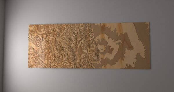
We start with the end: this is the piece in its final destination in Fort Collins, Colorado
Data Processing
The data type undergirding nearly all our projects is a digital elevation model (DEM). DEMs are raster (pixel-based) images where each pixel represents a square area of ground, and its greyscale value represents the elevation of that patch of land above sea level (dark=low, bright=high).
DEMs of U.S. landscapes are available for download from the United States Geological Survey and for global landscapes at Viewfinder Panoramas or OpenTopography. For a detailed overview of these and other key digital mapping resources, check out our earlier blog post.
After downloading the data (for this project, we used Japan’s ALOS data from OpenTopography), we re-projected to the Lambert azimuthal equal area projection and cropped to the desired aspect ratio using GDAL.
The client wanted a slice of Colorado extending from the Eastern to the Western edge, but narrower in the North-South direction. We elected to include Boulder through Pueblo, omitting the San Juans, but including the I-70 corridor. Here is the DEM that we used.

This is the digital elevation model (DEM) of the middle swath of Colorado
Rendering
Prior to green-lighting the project, the client understandably wanted an idea of what such a piece might look like. So I turned to some of our Perl scripts that we use to generate 3D renderings of each of our MiniCity models with realistic treatment of light. Take a look at these intricately-detailed posters that we offer at our store.
With some knowledge of the capabilities of CNC (computer-numerical control) machines, we decided that creating the piece from stacks of individual layers would be the most efficient. The alternative was to glue together a large and heavy slab of wood and carve the shape from that slab, like a sculpture. Several virtual tests showed that 16 layers allowed sufficient detail without excessive complexity.
Starting with the DEM as a 16-bit PNG image, I generated an outline of each of the 16 layers, converted each to 3D geometry in Gmsh, and ultimately rendered the collection of 3 million triangles on a virtual daylit wall using Radiance. As a side note, I’ve been using Radiance--a photometrically validated pseudo-radiosity raytracer--to generate realistic images for quite a while; it’s my go-to tool for complex visualization because it’s scriptable and accurate.
Radiance rendering of the proposed piece - this was the first indication of how awesome this would be
Sample
Since we had no back catalog of similarly large wood 3D models, we had to produce a smaller piece mirroring the final product in material and production methods--a model of a model, if you will. This was a great opportunity to test and refine our processes before committing to a major effort.
We chose a small portion of the full data, found 16 equal-spaced isolines of elevation, and leveraged AutoDesk Fusion 360 to convert those line drawings into toolpaths—commands for the Shopbot CNC machine to move the cutting bit. A big challenge here was to figure out how to get the Shopbot to cut our plywood pieces without slowing down on every spline curve (one easy-to-overlook setting in the driver software fixed this). In addition, we got to see what the polyurethane coat would look like on the Baltic birch.
The result was a 10”x10” terrain map (image below) of the area surrounding Colorado Springs and Pikes Peak. It had a warm color and reasonable terrain detail, but there wasn’t much contrast between the layers. This persuaded us to consider a two-tone design, with alternating layers of plywood being stained to appear darker (as appearing in the rendering above).

A 10”x10” sample in Baltic birch plywood, finished with wipe-on gel coat
Design
Lessons learned from the sample (alternate layer coloration, number and detail of layers, etc.) guided the final design. We selected 16 layers, which at ⅛” per layer would extend 2” from the base board. In addition, the sheer weight of the 10” sample compelled us to develop a method to create rectangular hollows in the structure of the model: each layer would have material removed to reduce weight, but still allow sufficient overlap with the layers above to allow solid bonding during assembly. We used ImageMagick to perform the image processing and morphological operations to allow the generation of the layers’ outlines.
Below is a sequence of images for layer 4 from various stages in the processing pipeline. The bottom images were used to generate toolpaths for the Shopbot.

Multiple stages in the digital design of the layers, showing hollow regions for weight reduction
Cutting
We ordered scads of wood from Boulter Plywood in Medford, MA: 14 sheets of 60”x60”x1/8” Baltic birch plywood, plus a 4’x8’x1/2” sheet for the base, all ripped to 42” width, and they arrived the next day - yay! We chose Baltic birch plywood because of its strength, but mostly because it is made of many more layers than standard American plywood, showcased by the many exposed edges.
Using the above series of bitmap images, we generated (vector-based) svg drawings, then converted those to dxf in Inkscape, loaded into Fusion 360 software (which doesn’t have a Linux version—-this is the only non-Linux step in our digital pipeline), and ultimately generated toolpaths for the Shopbot CNC machine.
We first had to mill a pocket into a 4’x8’ MDF sheet to make our spoil board, which accepted our trimmed 42”x60” sheets of birch plywood (recall the final size would be 116”x42”). Most of our cutting was done with a 60 degree V-bit at 12,000 rpm at 50 inches/second feed rate. $200 Worth of double-sided masking tape from Scotch and McMaster-Carr held down the plywood, while the Shopbot turned wood into dust.

One of the early layers being cut from a 42”x60”x1/8” piece of Baltic birch plywood
As the pieces were pulled from the CNC bed, they were all labelled with layer number, a part letter, and even a part sub-piece number in the event they didn’t survive being pried up from the double-sided tape.

These are only a few of the myriad sizes of pieces we had to catalog, sand, and stain
All, and I mean *all* edges of *all* pieces were hand sanded (finger-sanded, to be honest) to remove burrs and smooth out the final appearance. Because there were so many thin pieces, some inevitably broke, but we ensured that they all ended up in the correct place.

Wear a mask, kids - dust is bad for your lungs!
Staining
Getting the stain right was a challenge. Undiluted stain goes on heavy and dark. But diluted stain differs in its effect depending on the application technique and time allowed to set.
We opted for a 1:3 dilution with mineral spirits (measured by the gram on a postal scale), application with a foam brush (to make it easier to get the edges), and 2-3 minutes set time before wiping.
Nevertheless, all wood is different, and some panels came out a little darker or lighter than we expected. I’m a rocket scientist, so I wish everything was science, but, alas, wood is not. Fortunately, due to the 3D nature and alternating contrast in the final piece, any subtle variations are difficult to detect.
We organized each piece by layer number, intending to only stain the even layers. Despite this, we still stained some pieces from odd layers and forgot to stain pieces from even layers. Such is bookkeeping of puzzle pieces with power-law size distributions!

Testing two stain colors and three dilutions; sample Pikes Peak assemblies on the left

Staining area; a rag applies stain evenly, but a foam brush gets the edges
Assembly
Each layer had a guide sheet with the islands of land labelled and numbered. To place the pieces in their correct positions, we matched the labels that we wrote on the backs of each piece with the layer and number on the guide sheets. This took *much* longer than we estimated. Here is a photo of one of our guide sheets.

Where is piece 09-M?
We used at least two pounds of Titebond Original wood glue to attach all of the parts, smoothing the glue with a wood flange on large pieces, and with fingertips on complex and smaller pieces.
Each piece was clamped or held down with sandbags (6 mil locking vinyl bags from McMaster-Carr and 100 pounds of playground sand from Home Depot) for at least half an hour before moving on to the next piece.
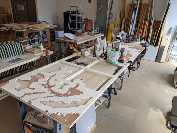
Gluing down the 4th layer - you can never have too many clamps!
Finishing
Boston mural artist Nate Swain lent me a hand with the finish - a coat of Varathane clear polyurethane, applied first with foam brushes, then touched up with a toothbrush. Yes, a toothbrush. This coating darkened the unstained wood and gave it a wonderful warm glow and also brought out a certain richness in the stained layers.

Nate did it with the foam brush in the shop.
Delivery
After a brief visit to the Artists For Humanity photo studio for some glamour shots, we wrapped the piece up with foam and stretch wrap to get it ready for shipment.

While ultimately the piece was crated, we only had to ensure its survival to the frame shop
BostonArt was gracious enough to send a truck to get the final piece, which, let me remind you, was nine and a half feet long, and weighed between 60 and 70 lbs!
I don’t normally nap during the day, but I did that day.
And there you have it: the step-by-step process of constructing a massive 3D map. The gratification of seeing the final product makes the process--entailing plenty of tedious manual labor, trial-and-error, and unforeseen obstacles--well worth it.
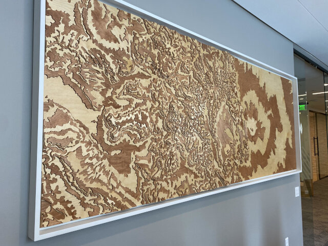
The finished piece on display in Fort Collins
Thanks
Obviously, I must thank a number of people who helped make this happen. Elizabeth at BostonArt was my go-between with the client, and a cheerleader when I needed one. Ryo at Artists For Humanity trained me on the Shopbot and gave me confidence when I didn’t have enough; Lorraine and Haidan at AFH facilitated the use of their work space, and John and Janna lent us their excellent photography skills. Nate, Suleiman, and Lauren showed up and sanded the many, many, small and large curved pieces that eventually went into the model. And, again, Lauren, my wife, encouraged me and supported me through the inevitable crises and breakthroughs that any big project entails.
If you’re interested in custom work by MiniCity.art, please contact us.
